What is a Tolerance Ring?
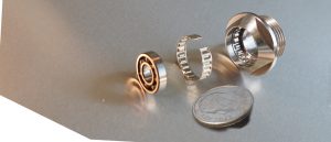
Tolerance rings are highly engineered frictional fasteners used to effectively join mating cylindrical parts. Manufactured from high quality spring steel or stainless steel strip, tolerance rings are widely accepted as fastening devices capable of handling torque transfer, axial retention and radial loading between mating and/or parts.
Technical and economical advantages ensured by use of tolerance rings include:
Rapid, low cost of assembly
Wider dimensional tolerance of mating diameters for interference fits compensation for Δ thermal expansion between mating materials
Elimination of keys, pins, adhesives, D-shafts, threads and splines
Compensation for small amounts of misalignment of up to 1/2° draft angle
Infinite rotational indexing of parts prior to assembly
Modification to spring rates/critical frequencies of assemblies
Basic Principal of the Tolerance Ring
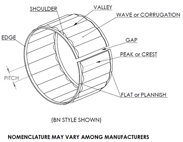
The tolerance ring is made from a thin spring steel strip of material into which waves, corrugations, or bumps are formed. The strips are cut to length and curled into the ring shape. The waves are either facing inward or outward to accommodate different applications. The AN style, waves facing inward, is designed so that the ends can be closed and fitted into a bore or tube and is self-retaining when released. The BN style, waves facing outward, is designed so that when the ends are opened it will slip over a shaft and also be self-retaining when released.
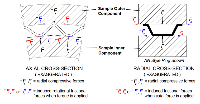
The waveforms of a tolerance ring are designed to exert a holding force yet allow for ease of assembly between mating components. When the tolerance ring is assembled between mating components, each wave elastically deflects, resulting in holding force. The holding ability of the ring is the resultant force of all the waves and the coefficient of friction with the mating components.
PLEASE NOTE: Below are some formulas and concepts for those with advanced understanding and experience working with tolerance rings. However, we recommend contacting us with your particular application by submitting the design constraints in a properly filled out New Project Information Form.
These formulas do not account for tooling inventories, available pitches, material limitations and other various nuances. They are to be used for guidance only in determining an order of magnitude and provide theoretical approximate values which can vary from actual results.
E= Modulus of elasticity or Young’s modulus, typically 26×106 psi to 31×106 psi for steel materials
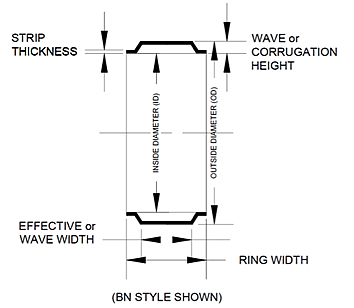
t = strip or raw material thickness, [inches]
p = pitch, distance between waves, [inches]
w = effective, wave or tool width, [inches]
c = constant which can vary from about 3 to 7, but 4.8 and 6.0 are common values
k ≈ cEw(t/p)3 = simplified theoretical spring constant of a single wave or corrugation, also referred to as “little k”, [lbs./inch]
h = nominal wave or corrugation height, this is a reference dimension since tolerance rings function by the principle of elastic averaging
Δh = amount of wave compression or wave deflection, [inches]
Dq = inner component OD + 2h if AN style ring, outer component ID – 2h if BN style ring, [inches]
N = πDq/p = approximate number of waves or corrugations on circumference of tolerance ring
µS = static coefficient of friction, typically 0.15 for steel on steel
Fr = (Δh)k = radial spring force exerted by a single wave or corrugation, [lbs.]
FR = ∑Fr = (Δh)kN = total radial circumferential load, [lbs.]
FA = µS FR = µS (Δh)kN = µS ∑Fr = peak axial retention force or maximum pull-out force
K ≈ kN/5 = theoretical encountered spring rate when the inner component is moved radially relative to the outer component within the elastic range of the tolerance ring, also referred to as “big K”, [lbs./inch]
d = inner component nominal OD, [inches]
T = 0.5d(FA) = 0.5d(Δh)kNμs = theoretical maximum torque hold prior to rotational slippage based on the amount of wave compression, [inch-lbs.]
FM ≈ zkNh/5 = approximate radial capacity = maximum radial load that can be endured prior to yielding. This occurs when the waves are compressed towards the end of their elastic range, which typically varies from 10% to 18% compression depending on the particular configuration, [lbs.]
z = percentage value constant which typically ranges from 0.10 to 0.18