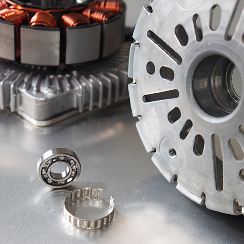


Bearing Mount
Tolerance rings can prevent the loss of retention experienced when mounting steel bearings to a housing with a different rate of thermal expansion.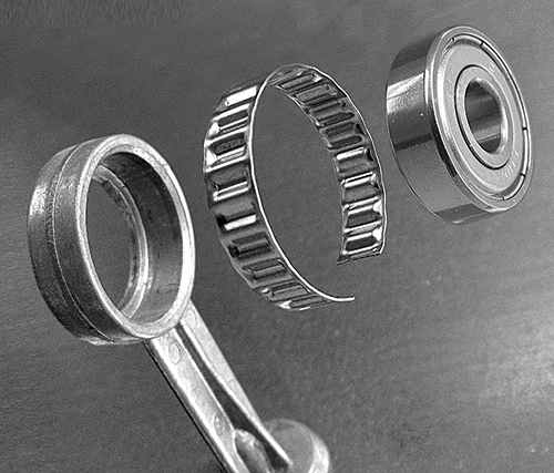
Noise and Vibration
Noise and Vibration reduction can be critical to electric motors. Tolerance rings may can be used to reduce noise and vibration by shifting the harmonics. Bearings and stators can be secured to their mated components to prevent failure.
Dissimilar Materials
When two different materials are used in an application, their individual coefficients of thermal expansion may cause problematic gaps. A tolerance ring can be used to take up this difference, providing the necessary ‘bridge’. This allows for manufacturing options such as using lighter or more cost-effective materials.